| RECONDITIONING-C64 | ||||||
| Showing 41 - 60 of 96 pictures [ « Previous | Next » ] | ||||||
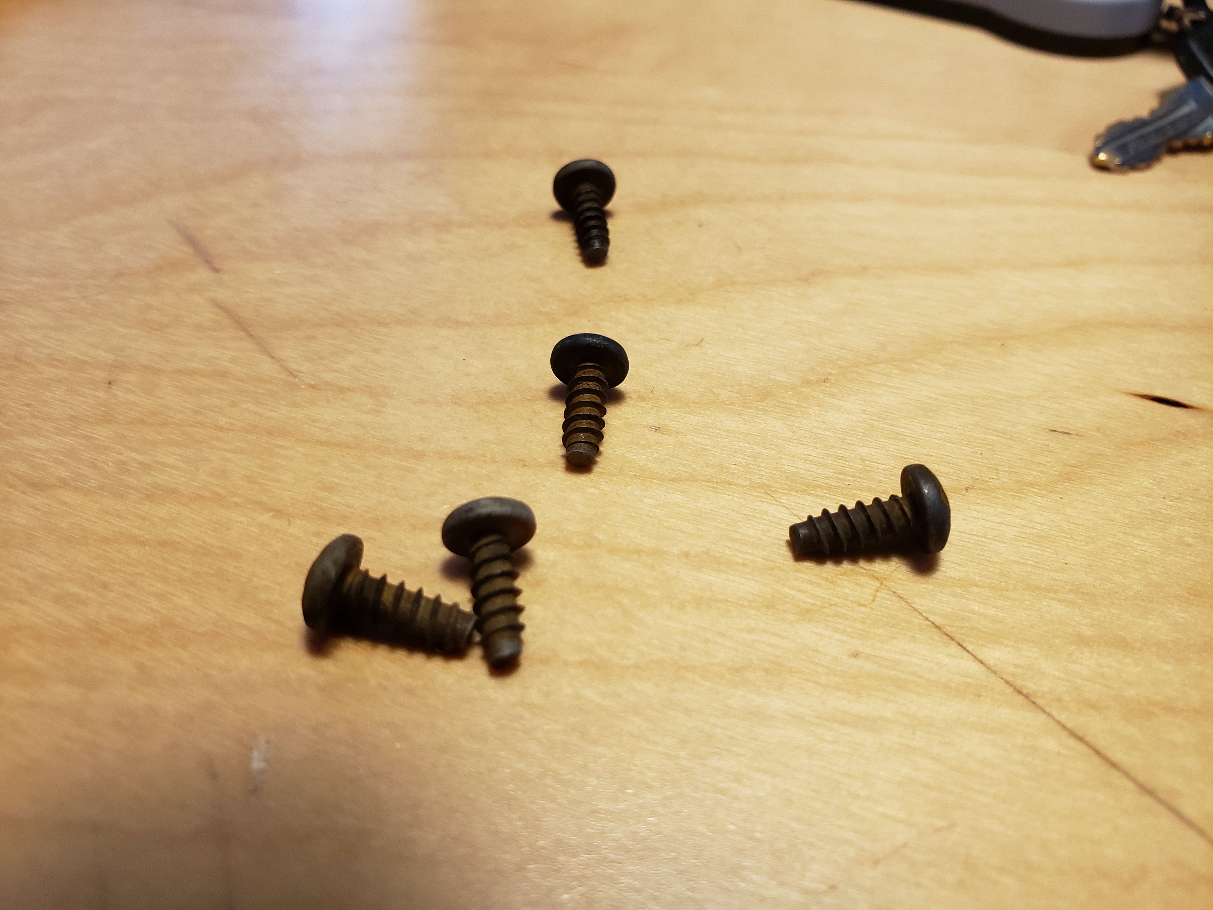 20200416_143017.jpg Technically, those screws are cleaned up. In reality, they're a bit worse for wear after a bath in vinegar. |
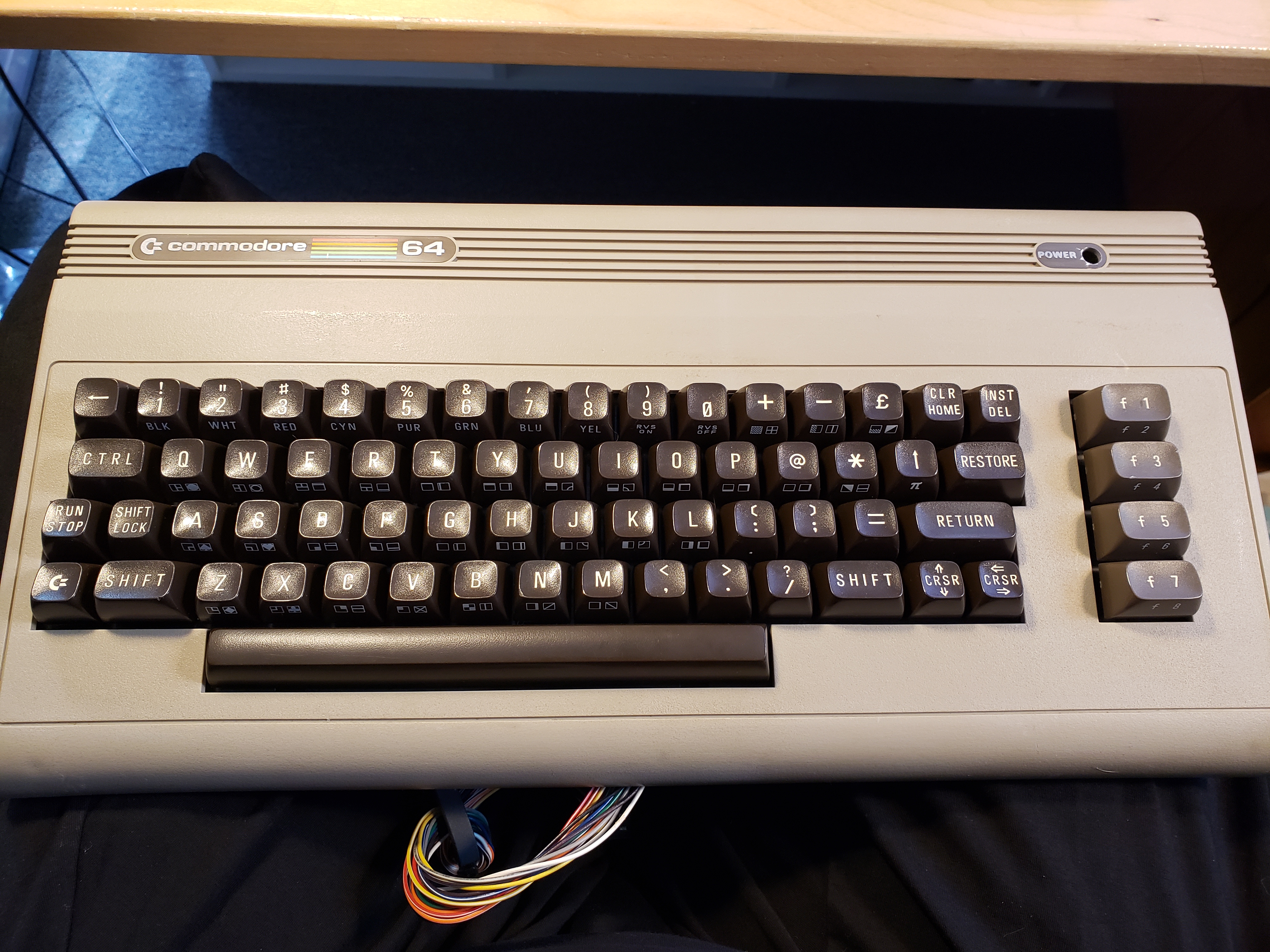 20200416_143156.jpg Upper half almost back together. The power LED in the top right wasn't back in. |
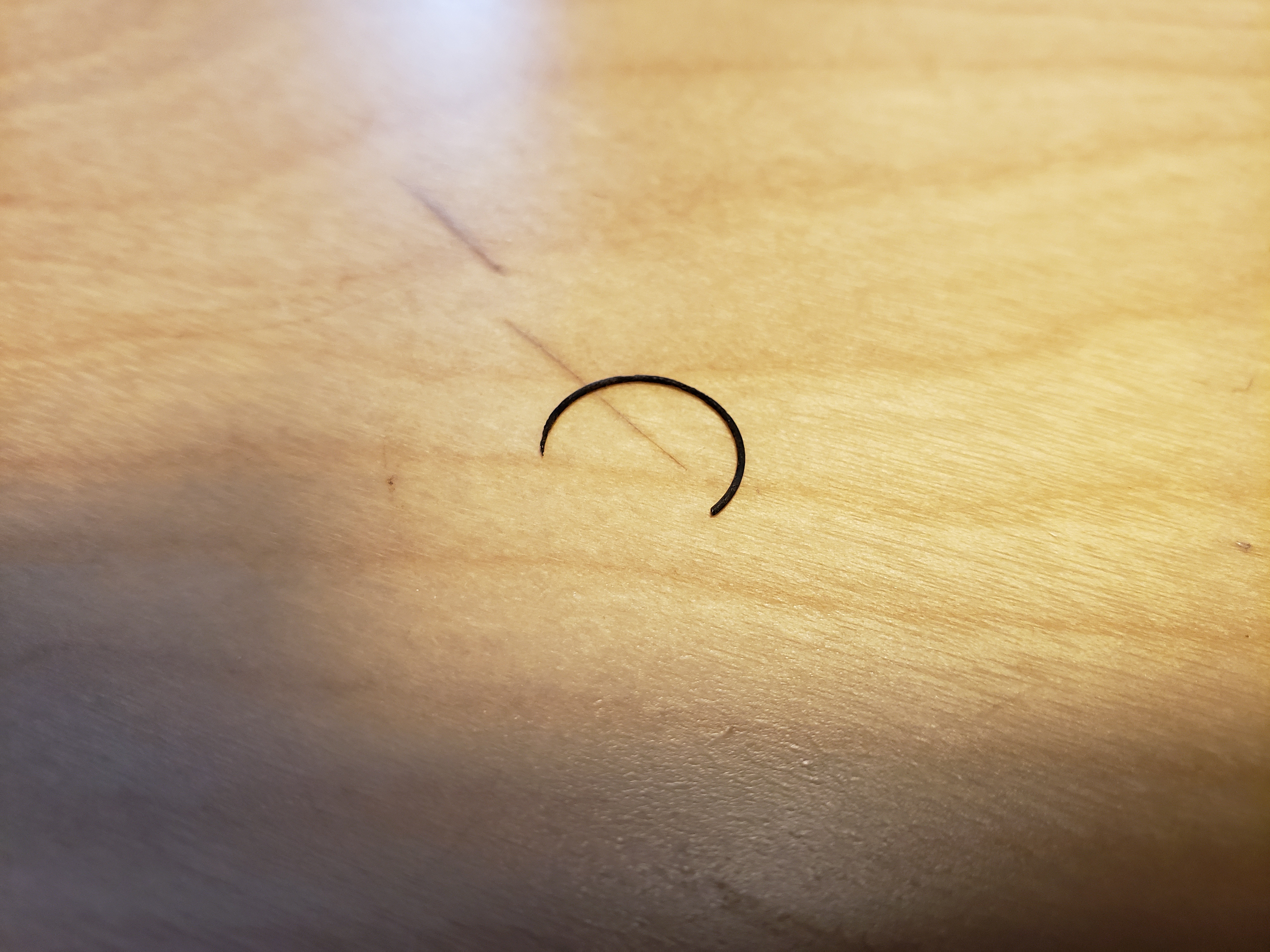 20200416_143452.jpg Part of a keyboard spring that broke off. |
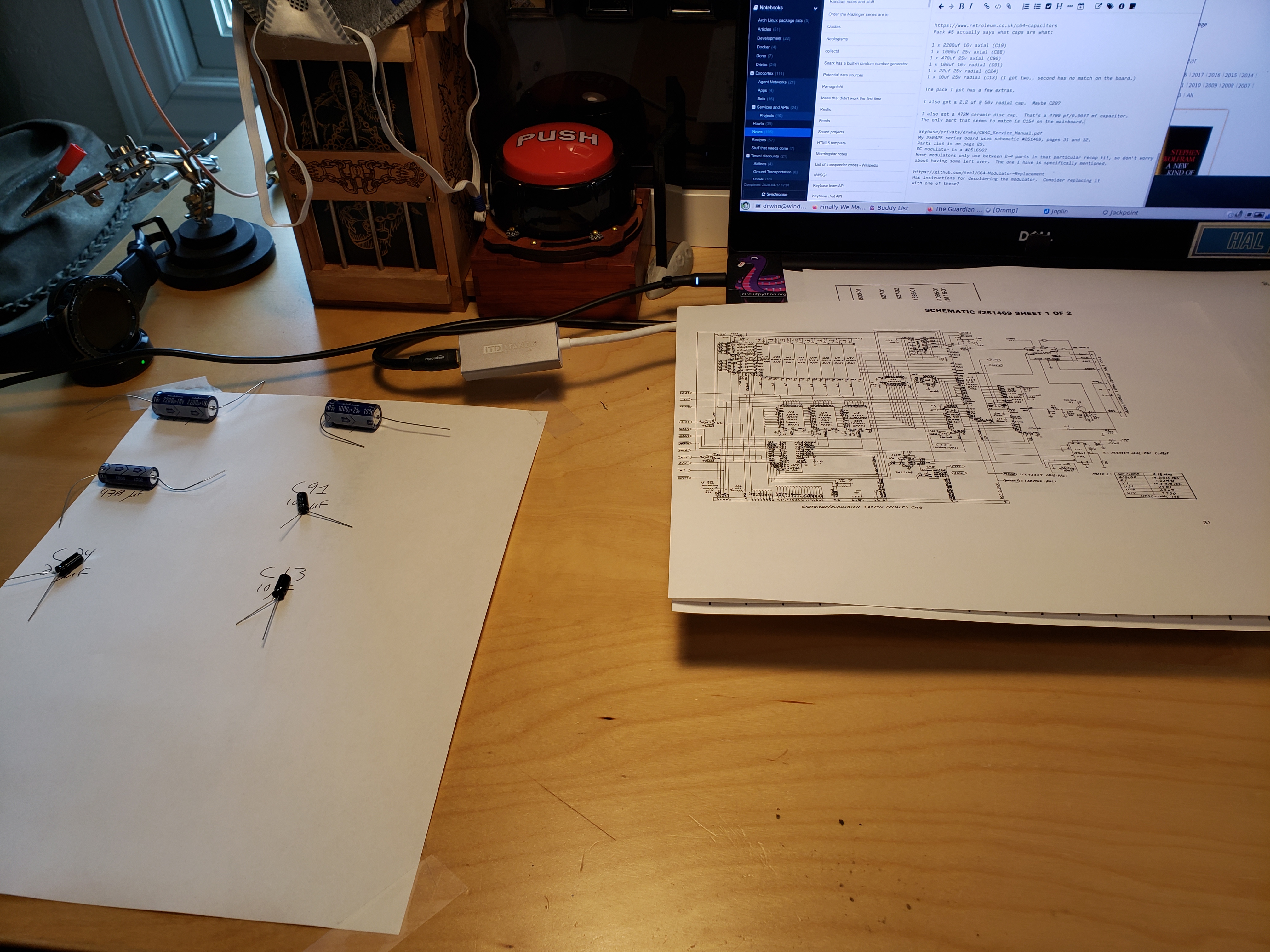 20200417_170514.jpg Knolling the replacement capacitors before installation. | |||
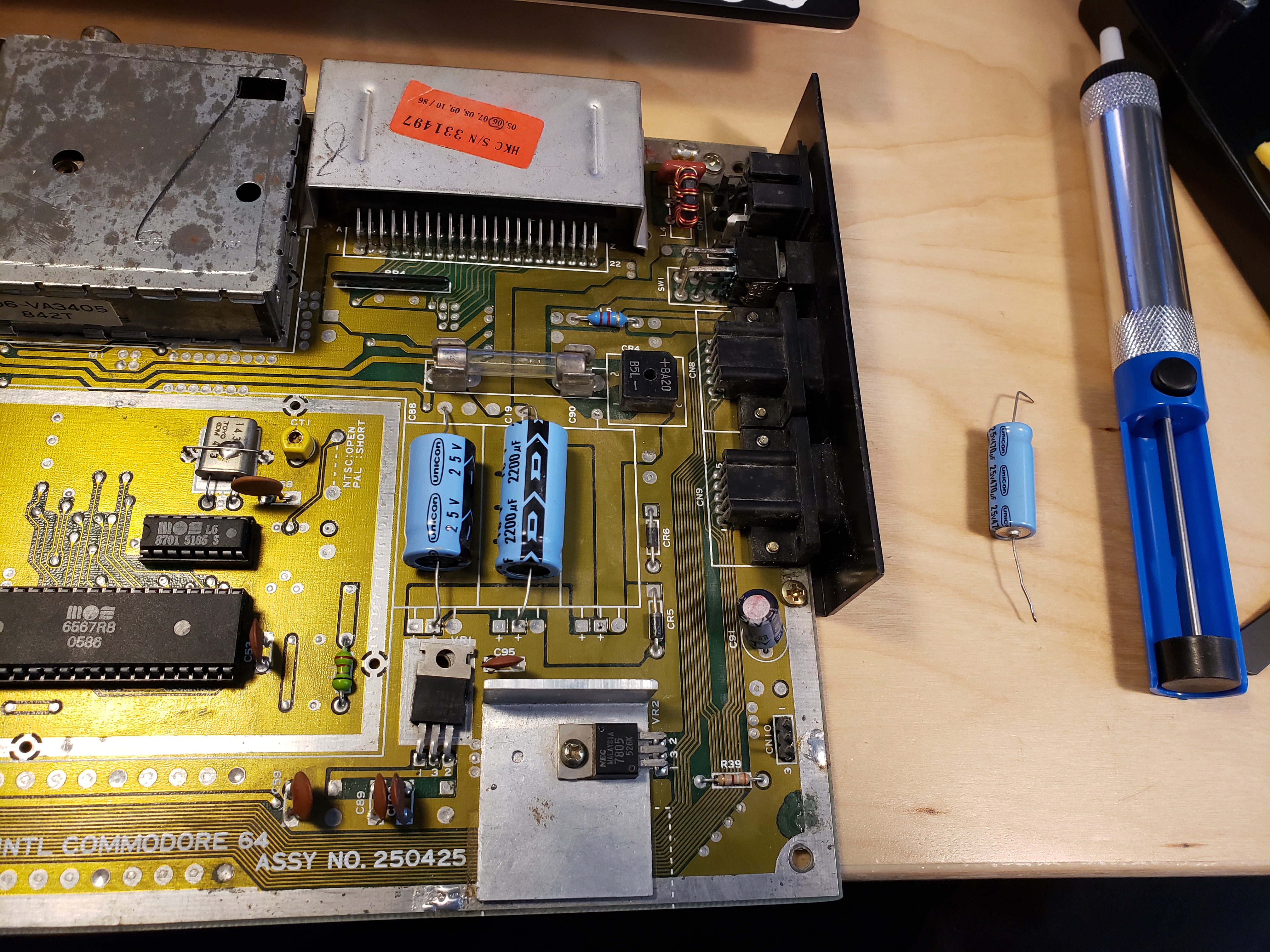 20200417_171154.jpg Power smoothing caps before replacement. |
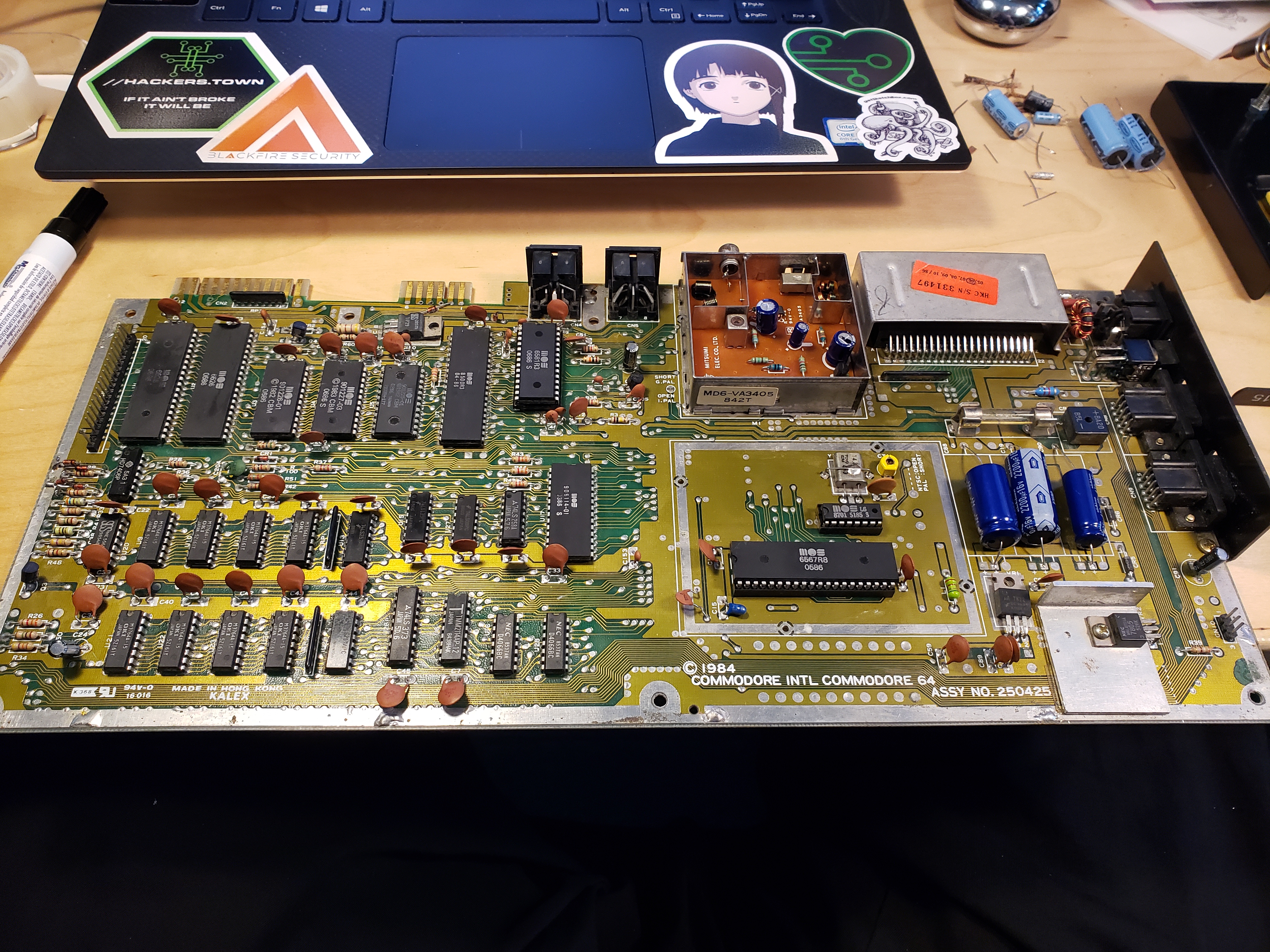 20200417_175020.jpg New power smoothing caps. Moving on to the rest of the board. |
 20200417_175030.jpg |
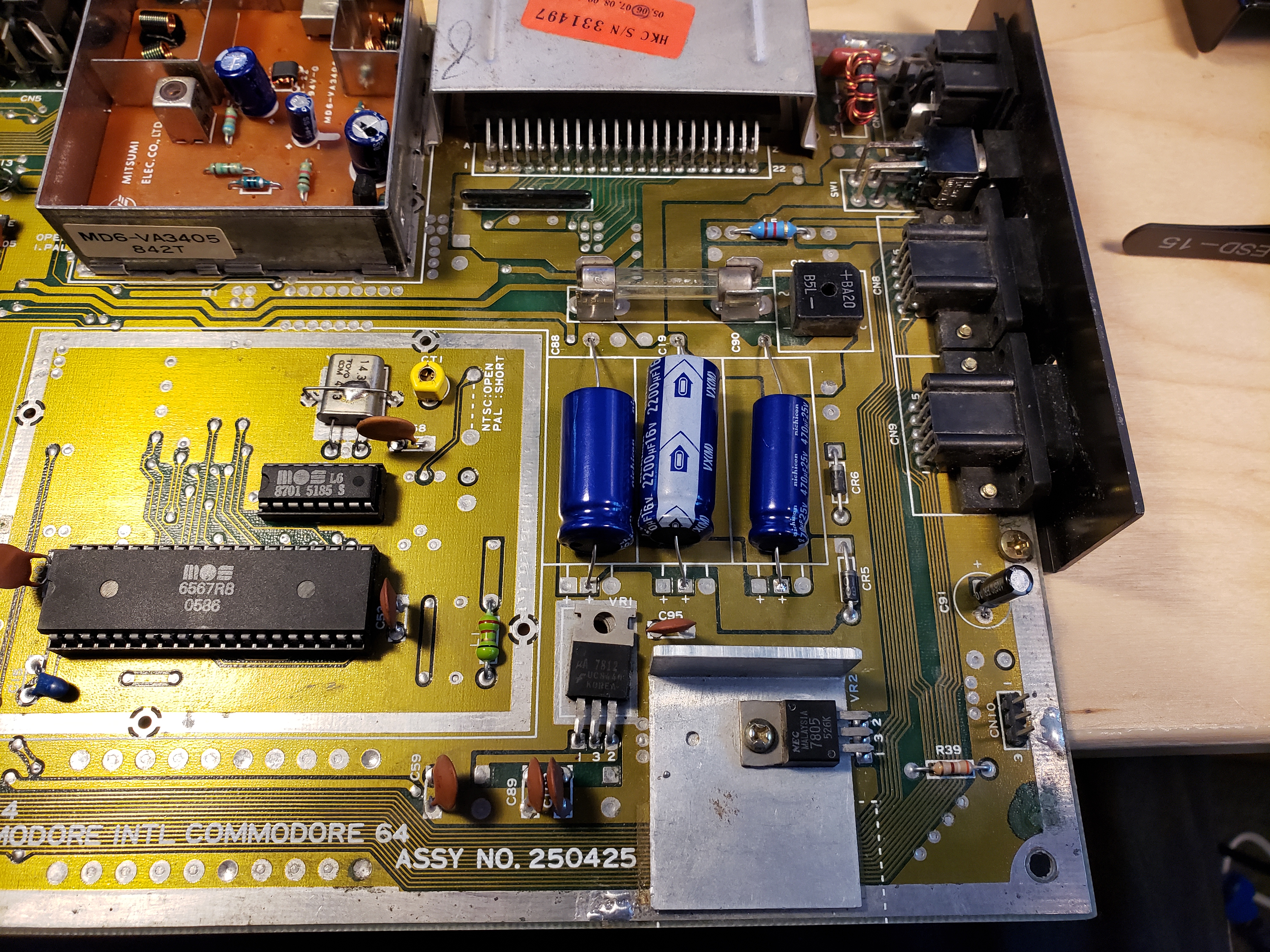
 20200417_175042.jpg Not too shabby if I do say so myself. | |||
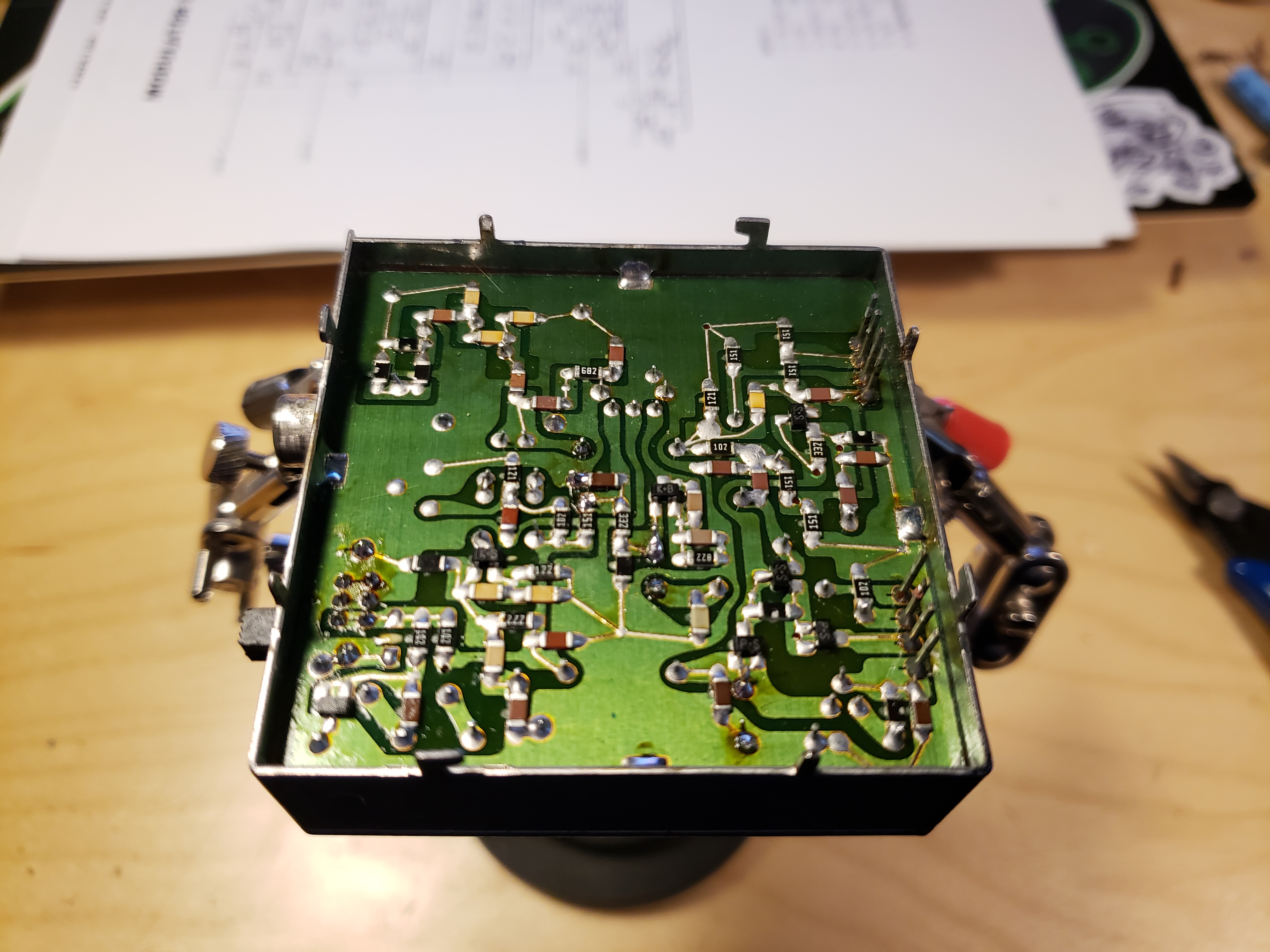 20200417_185144.jpg The underside of the RF modulator. Lots of surface mount components made it tricky to find the through-hole solder points. |
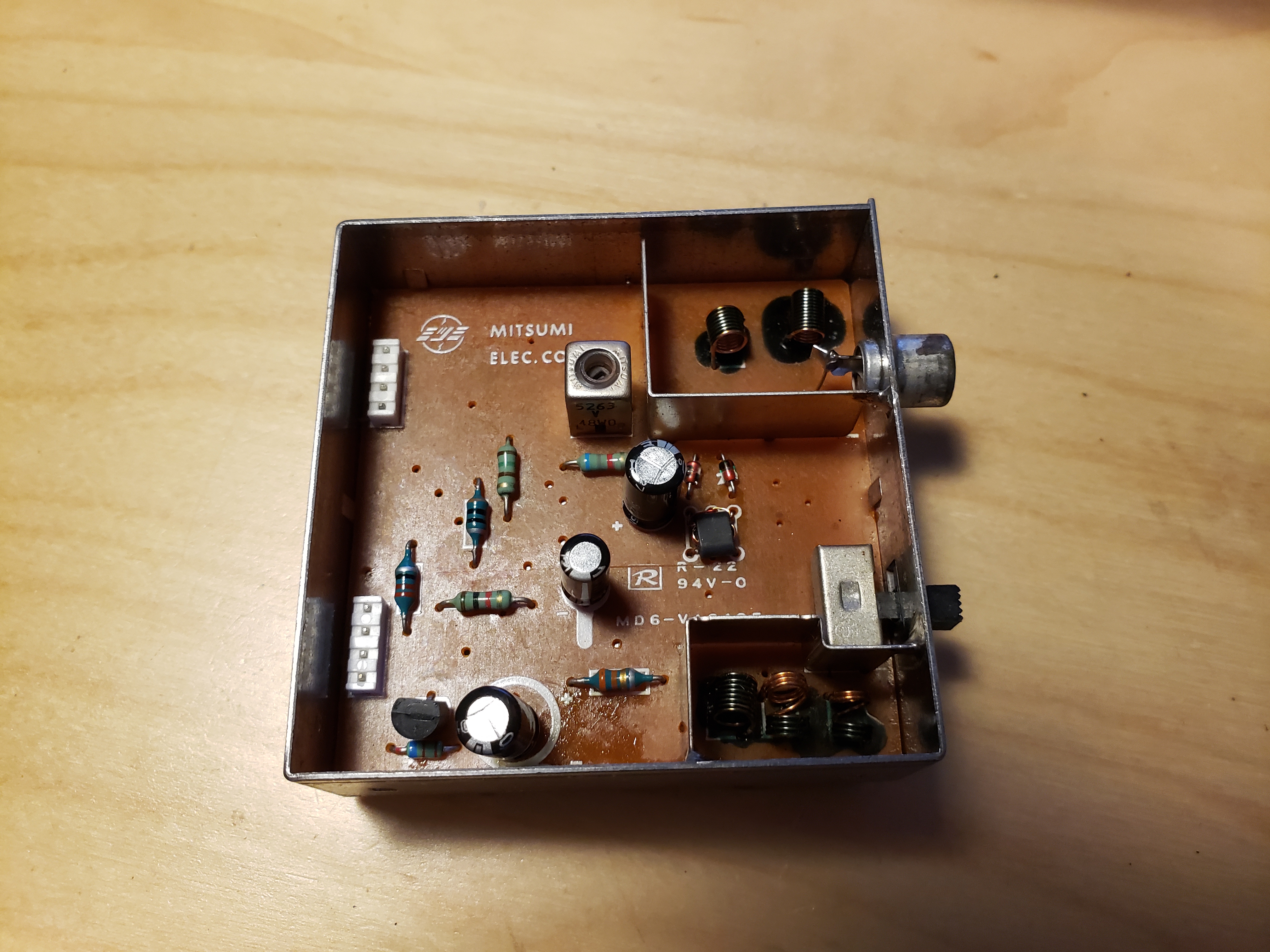 20200417_185208.jpg Top side of the RF modulator. Not many components up here, but there wasn't a whole lot of room to maneuver in there. |
 20200421_185733.jpg Time to reassemble. |
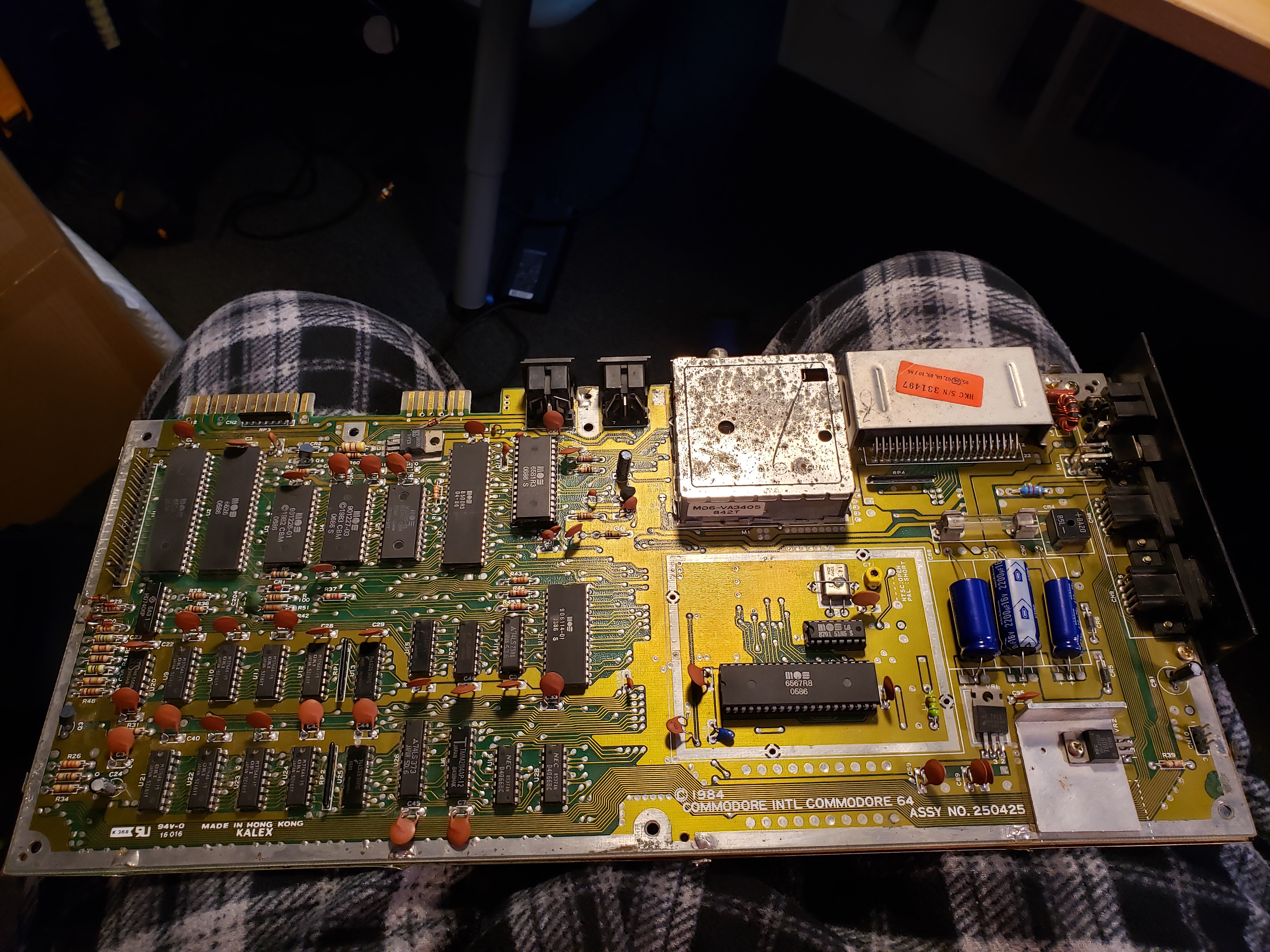
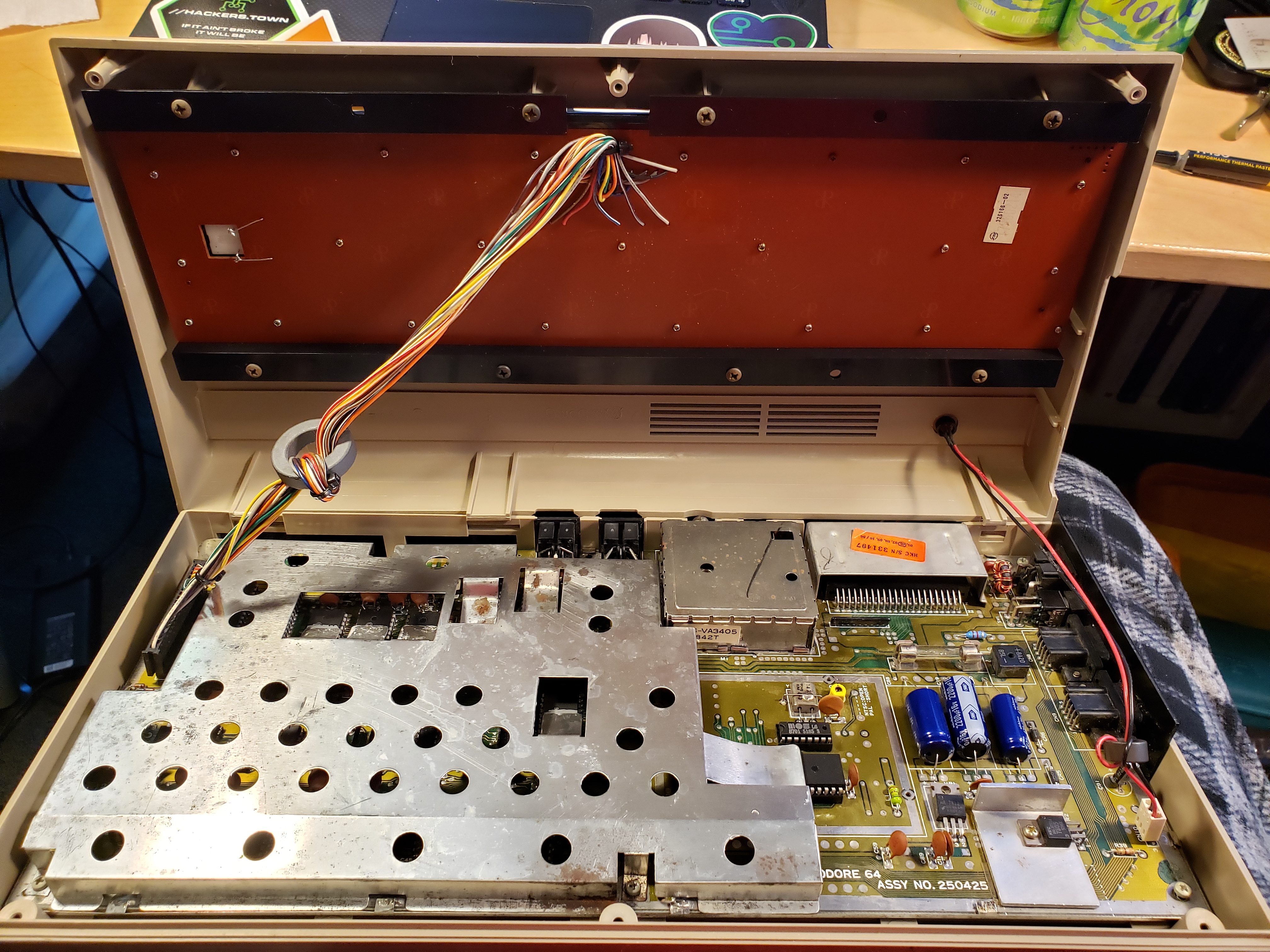
 20200421_190041.jpg Let's get that mainboard screwed down. | |||
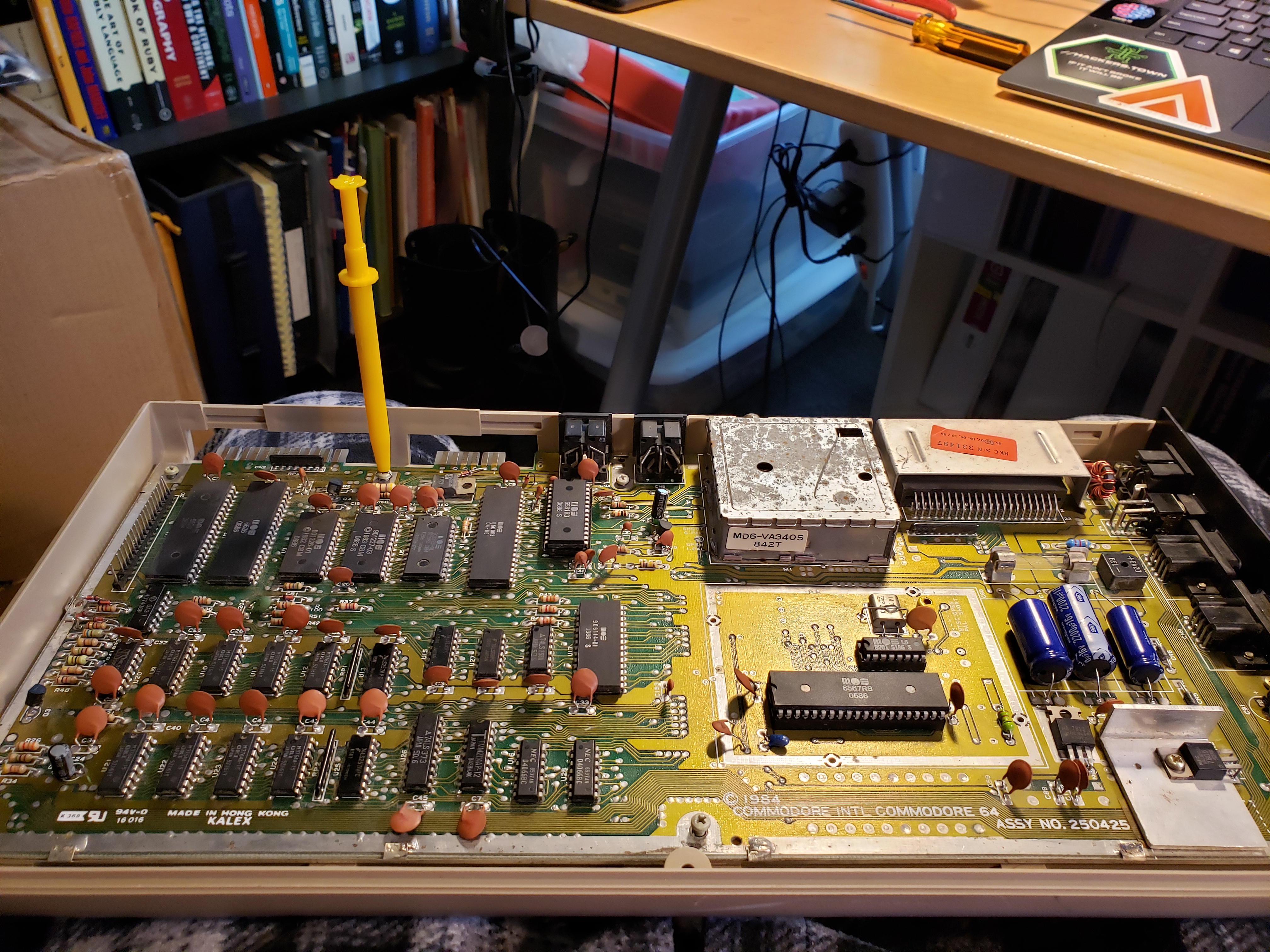
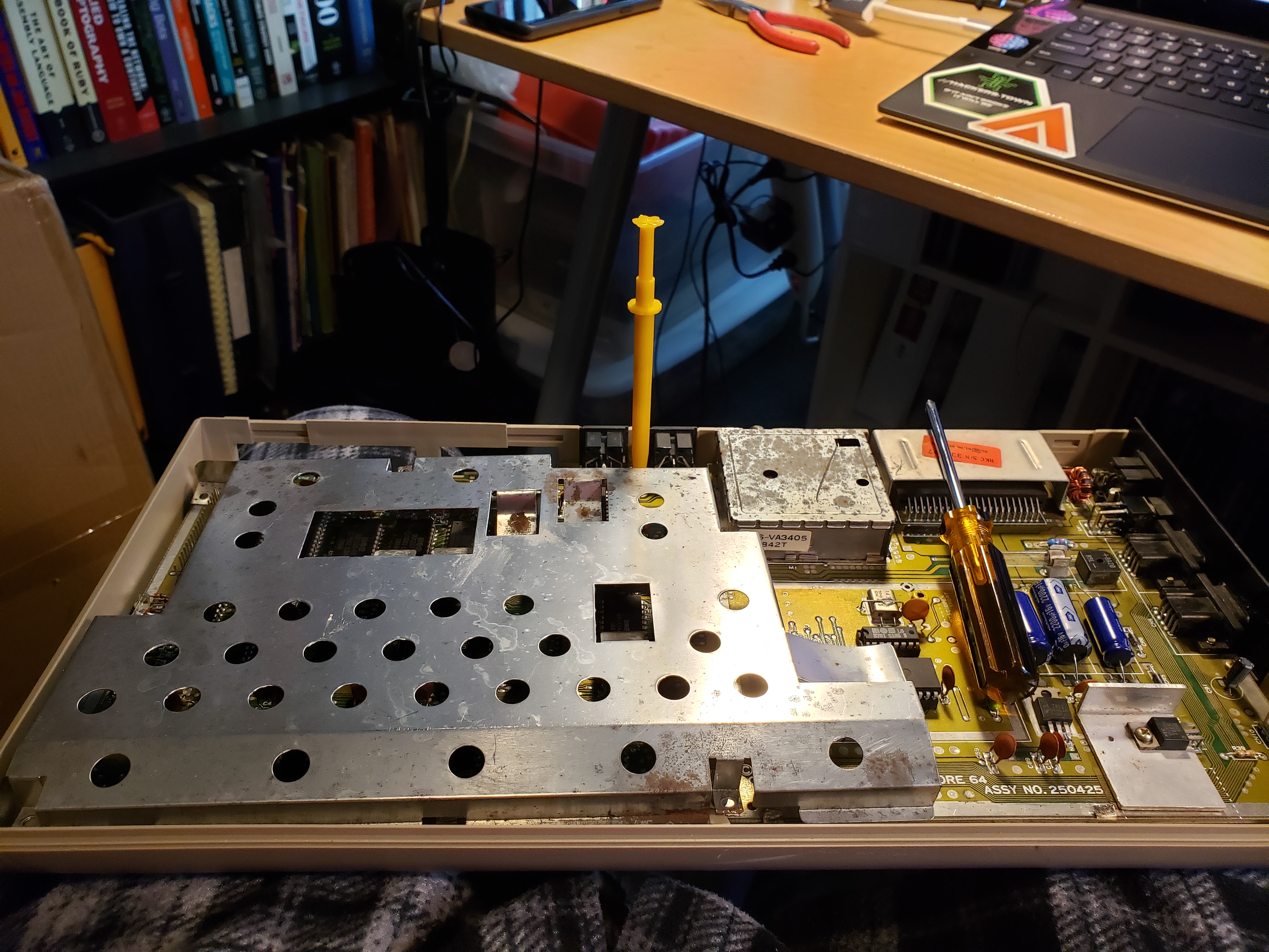 20200421_190132.jpg Let's get that mainboard unscrewed because it also holds the RF shield in place. Oops. |
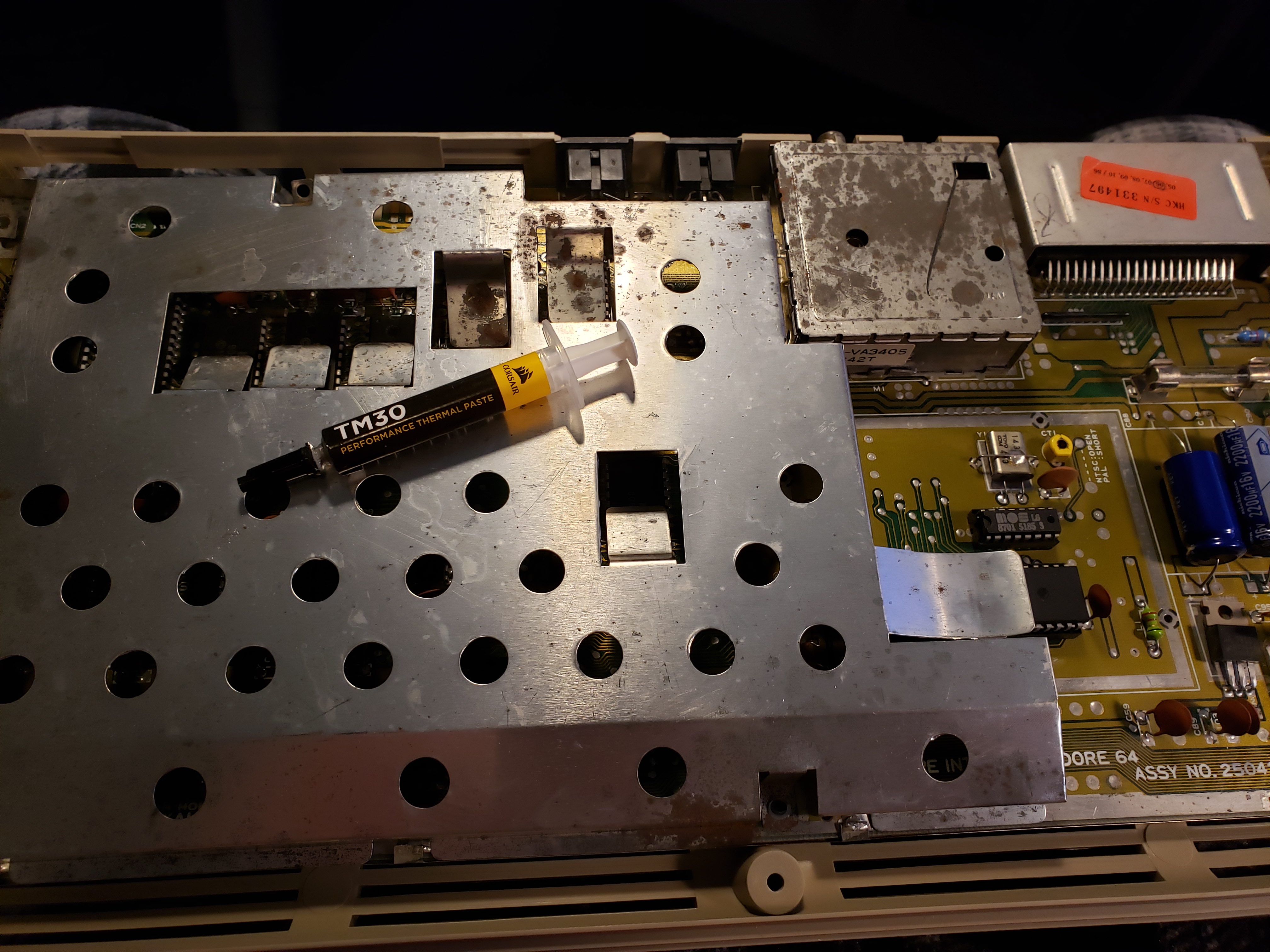 20200421_190551.jpg While we're at it, let's replace the heatsink grease. |
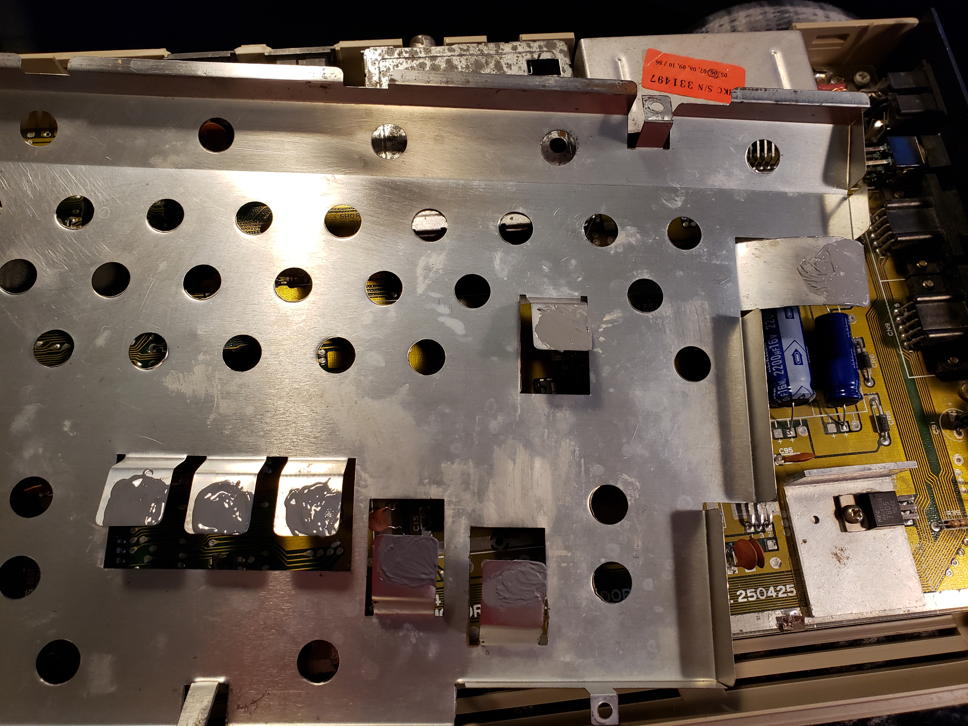 20200421_190730.jpg To save money, Commodore used the RF shield as the heat sink for some of the chips. |
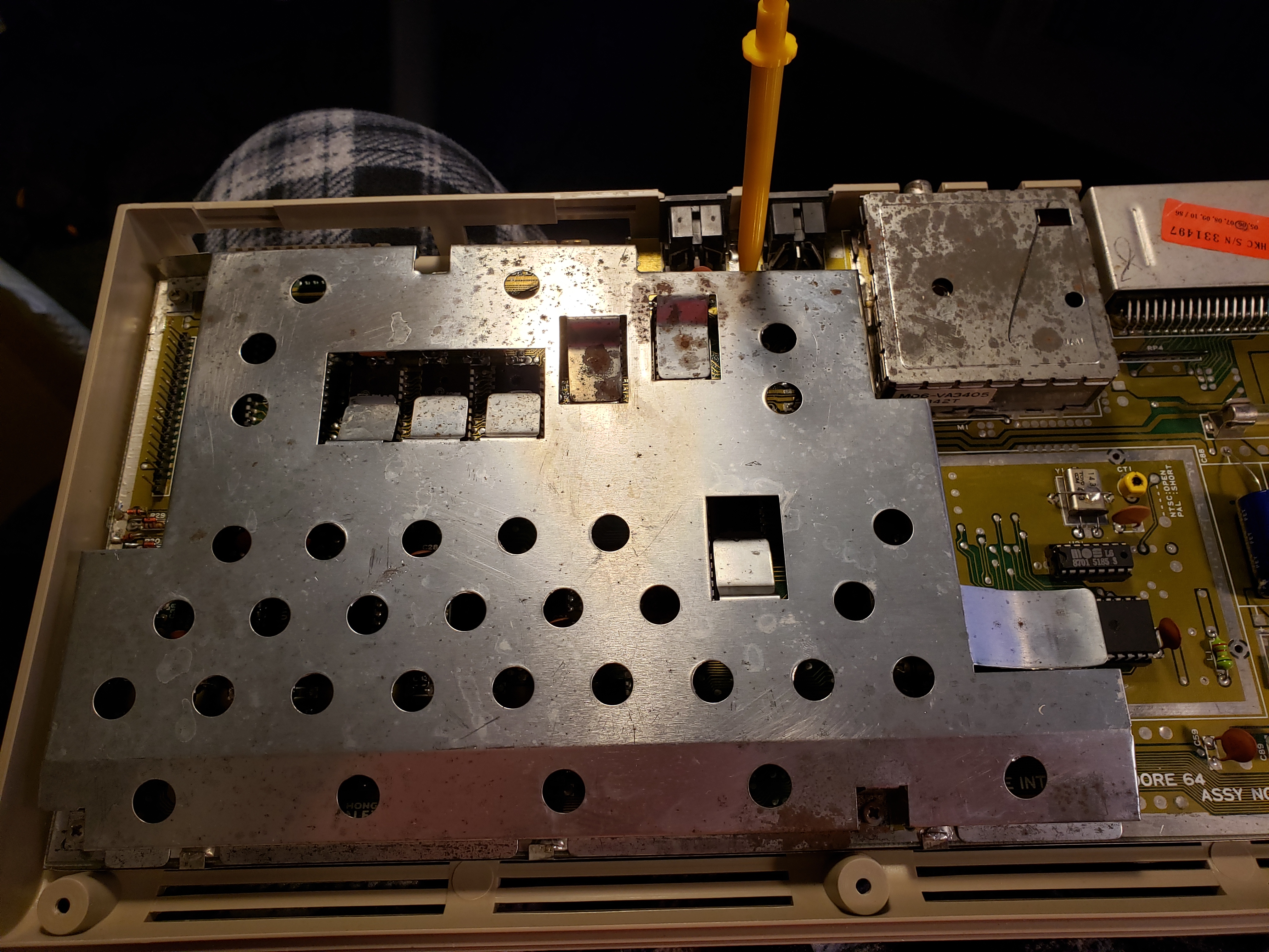 20200421_191018.jpg Did it right this time. | |||
 20200421_191519.jpg Plugging the upper half into the lower half. |
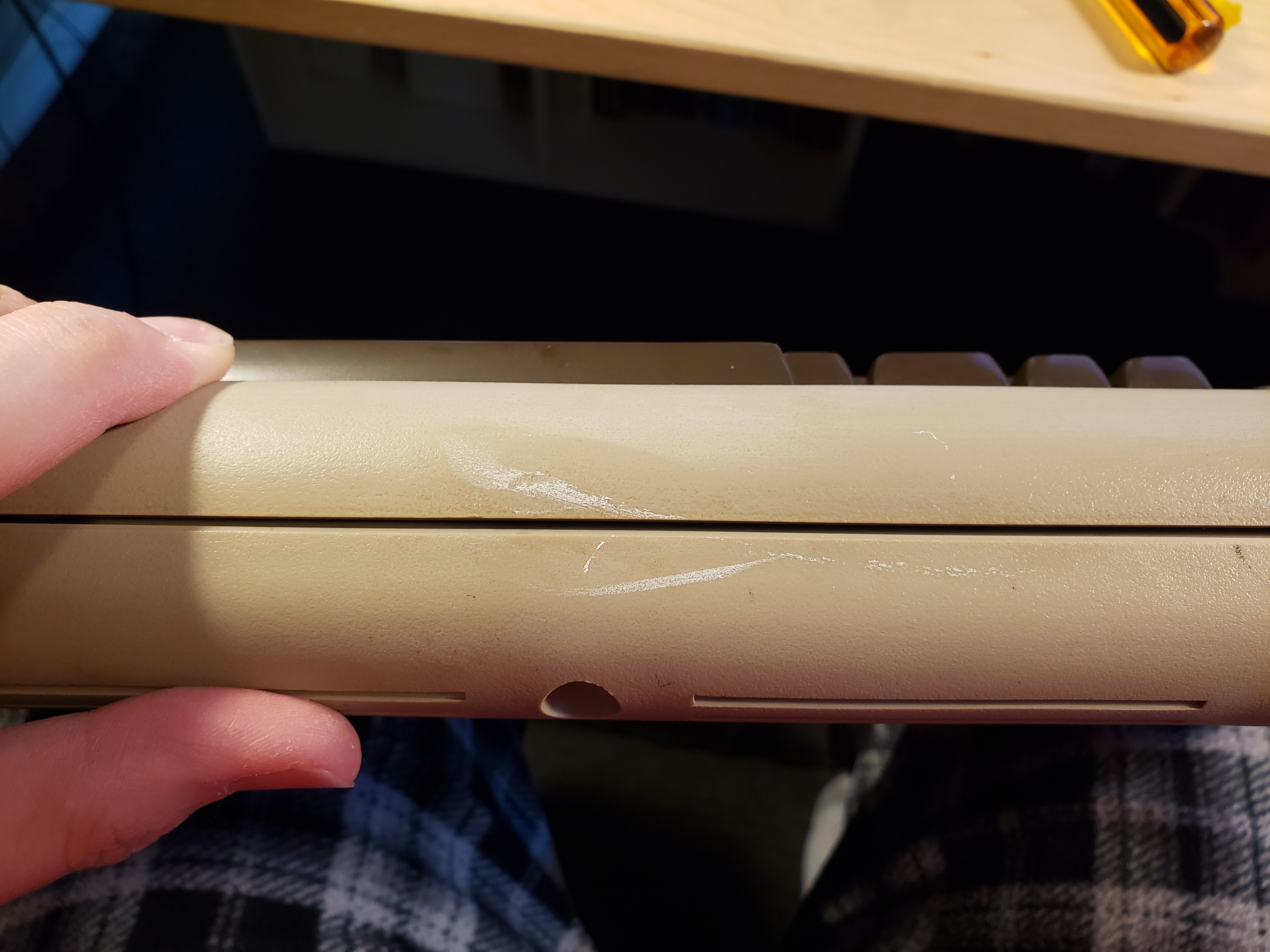 20200421_191559.jpg I thought I cleaned up the shell. I was wrong. |
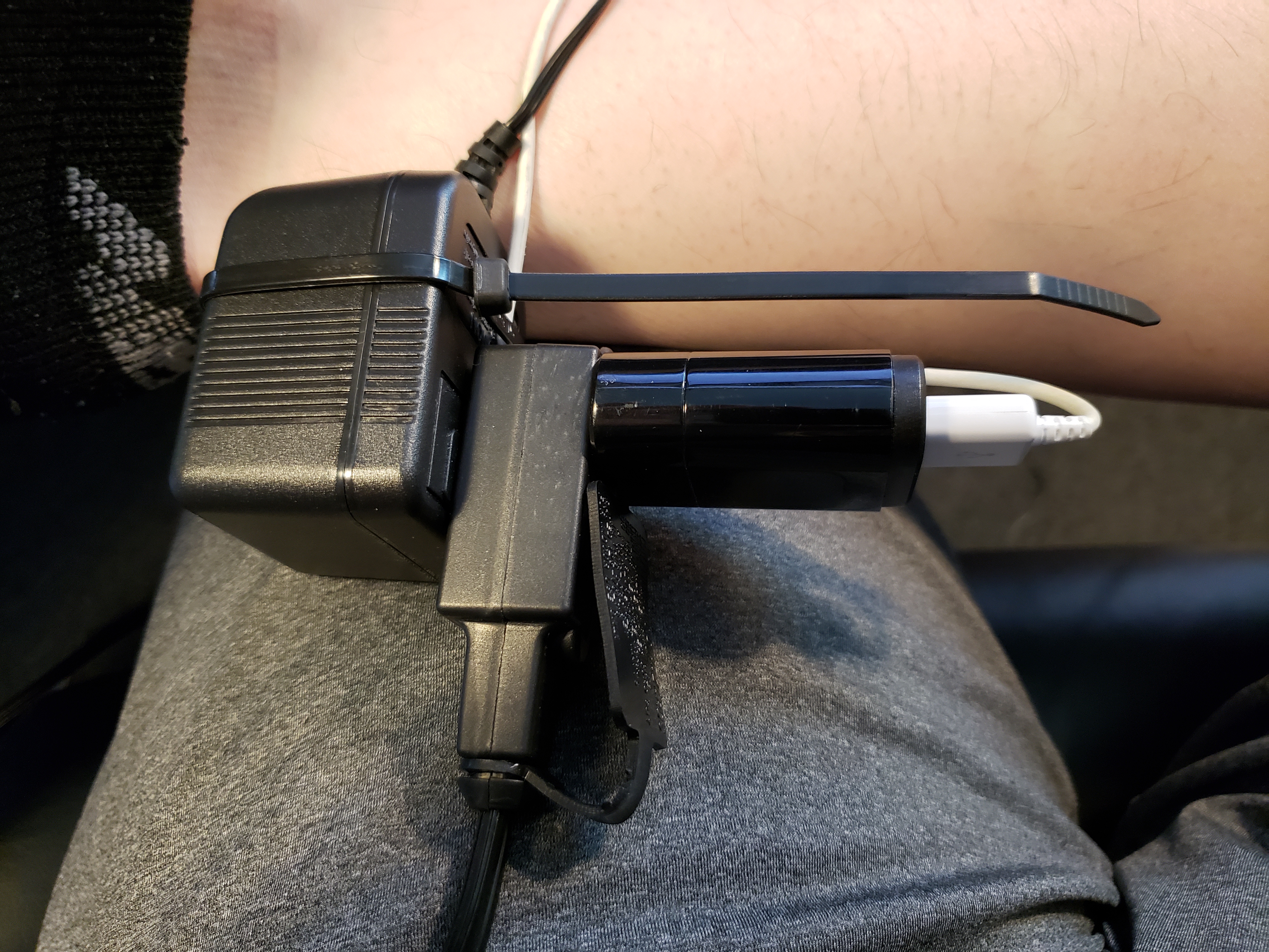 20200422_154419.jpg Building a replacement power supply. |
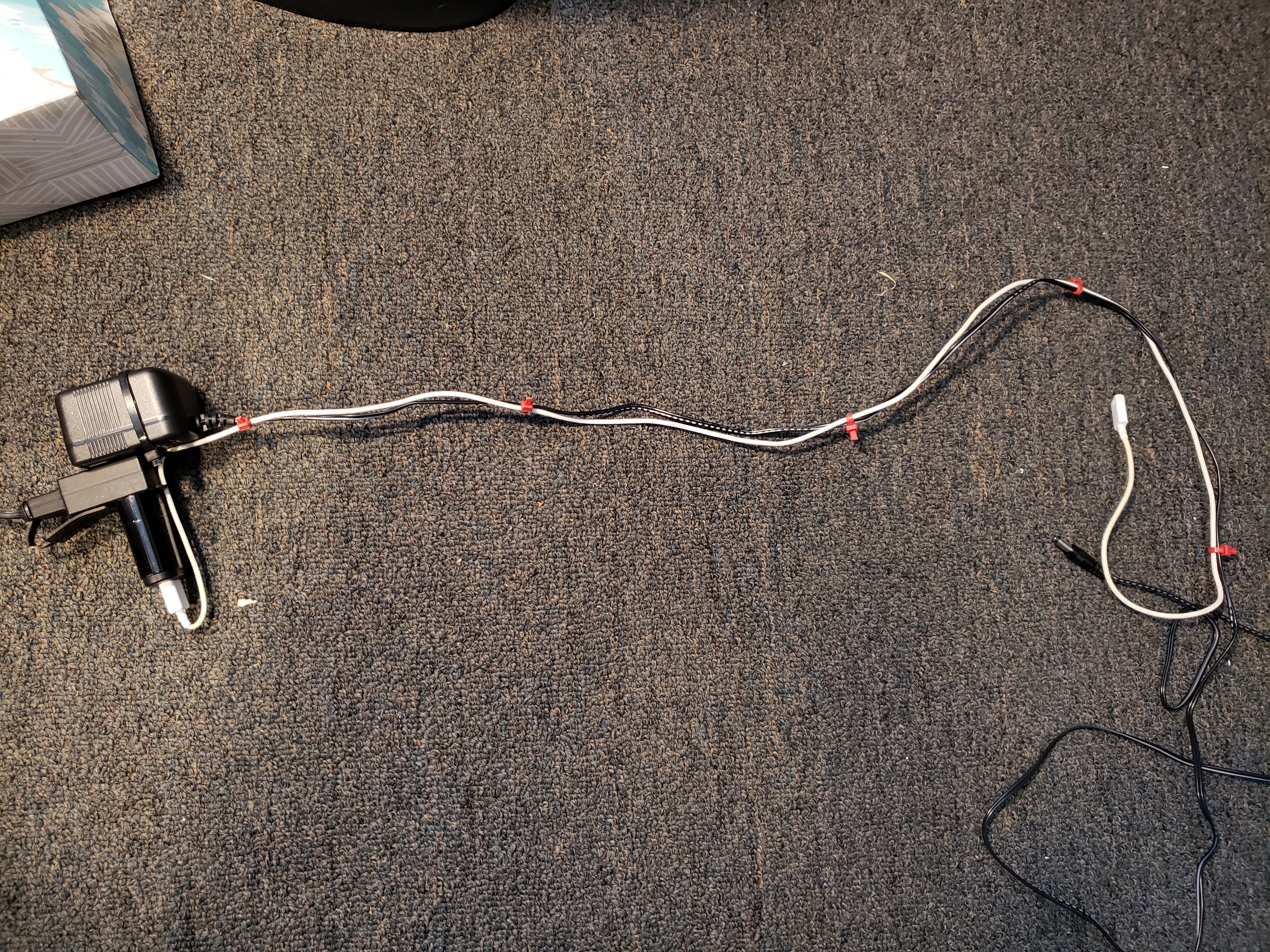 20200422_154750.jpg | |||
| Showing 41 - 60 of 96 pictures [ « Previous | Next » ] | ||||||